Professional FDM: Welcome Home, Stratasys Dimension 768!
In June of 2014 I was lucky enough to snag a functional Stratasys FDM machine on eBay for a few thousand dollars -- mere pennies compared to what a comparable machine would cost new today (~$30,000). It had to be shipped over from Boston, though; a voyage that I know from personal experience can take its toll on tired travelers!
The printer wasn't fastened properly during the trip, and got back to me with a broken front glass panel and smashed rear circuit breaker. That's what you get for bargain "blanket wrap" shipping, I suppose. Thankfully, I was able to find a replacement part for the circuit breaker on DigiKey that got to me within a couple of days -- that had the printer up and running quickly.
The printer wasn't fastened properly during the trip, and got back to me with a broken front glass panel and smashed rear circuit breaker. That's what you get for bargain "blanket wrap" shipping, I suppose. Thankfully, I was able to find a replacement part for the circuit breaker on DigiKey that got to me within a couple of days -- that had the printer up and running quickly.
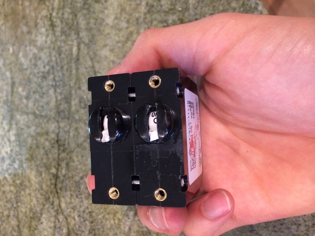
The broken breaker.
|
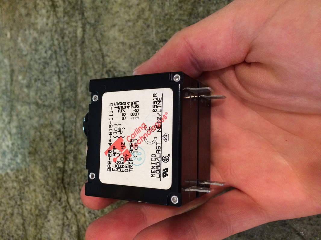
Thankfully it had a spec sticker on it, which made replacement easy.
|
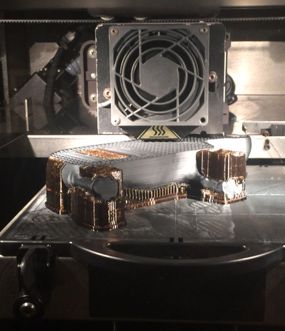
Did you even need to guess what my first print was? A hippo, of course!
|
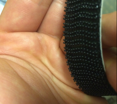
The entire glass panel was held in place using only this "super velcro." Both sides of it are the same, and consist of mushroom-topped heads that interlock. I wonder what the injection-molding process looks like to make this velcro...
|
Unfortunately, the glory days were relatively short lived. Within a couple of weeks I began to notice irregular noises coming from the build chamber during rapid movements, and felt high levels of resistance when I tried to move the print head manually (for example when adjusting the tip wipe assembly). My first instinct was to better lubricate the guide rods, which were bone dry and beginning to show very slight signs of corrosion.
No matter how much penetrating oil I poured into the bearings, they showed no signs of loosening up. Sometimes, after aggressive oiling, they'd free up (especially when the build chamber was heated to its 75C set point) but they quickly seized back up upon cool down. In order to troubleshoot the problem further, I removed the side panels of the printer to expose its guts and proceeded to disconnect the stepper motors that powered the X and Y axes. I suspected that a partial short in these motors or their drivers could be responsible for locking up the axes upon power down. However, even after decoupling the linear carriage from the stepper motors, it continued to bind: the issue was probably bad bearings.
No matter how much penetrating oil I poured into the bearings, they showed no signs of loosening up. Sometimes, after aggressive oiling, they'd free up (especially when the build chamber was heated to its 75C set point) but they quickly seized back up upon cool down. In order to troubleshoot the problem further, I removed the side panels of the printer to expose its guts and proceeded to disconnect the stepper motors that powered the X and Y axes. I suspected that a partial short in these motors or their drivers could be responsible for locking up the axes upon power down. However, even after decoupling the linear carriage from the stepper motors, it continued to bind: the issue was probably bad bearings.
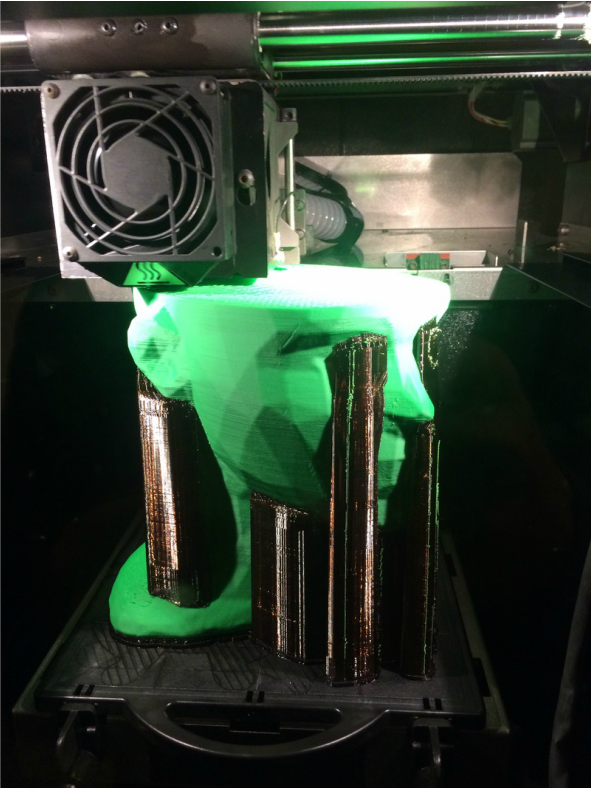
My first massive test build: a head model from the web that I modified by heavily "decimating" in software to make extra polygonal.
|
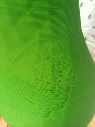
Small issues like this often plagued prints: defects were most common on the top surface of sparse-fill parts, and were likely due to the print head binding up slightly during the contour process.
|
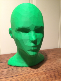
The finished product, 34 hours later.
Despite any issues, the prints were coming out pretty well overall. Acetone polishing any large surfaces made them appear flawless.
|
After debating whether or not I wanted to tear into the machine and replace these bearings, knowing full well that any mistake during the process could result in a "bricked" machine, I decided to go ahead and begin. Any failure would be a learning experience, and I knew from my previous interactions with the Stratasys support team that parts for these machines were hard to come by and that repair techs were out of my budget. If I continued using the machine in its current state, a driver board or stepper would almost certainly blow due to an over current; finding replacement electronics would probably be much harder and more expensive than replacing the bearings now.
Ripping apart the printer was relatively easy, but I was not convinced that it would go back together nicely. In my frenzy to find the root cause of the XY table's resistance, I ended up doing a pretty lousy job of documenting where parts went. I'd just have to rely on my well-practiced (but sometimes misleading) spidey-sense when putting it back together. Also, I should mention that throughout the process I was very impressed with the build quality of the 768. Every piece seemed very well designed and robust -- it was really fun for me to imagine the design considerations that Stratasys employees must have wrangled with during the creation of this machine.
Ripping apart the printer was relatively easy, but I was not convinced that it would go back together nicely. In my frenzy to find the root cause of the XY table's resistance, I ended up doing a pretty lousy job of documenting where parts went. I'd just have to rely on my well-practiced (but sometimes misleading) spidey-sense when putting it back together. Also, I should mention that throughout the process I was very impressed with the build quality of the 768. Every piece seemed very well designed and robust -- it was really fun for me to imagine the design considerations that Stratasys employees must have wrangled with during the creation of this machine.
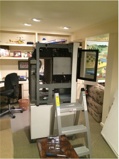
The family room of the Schneider house: probably not a typical place to find a Stratasys FDM machine! You can see some of my old RC helicopters in the background.
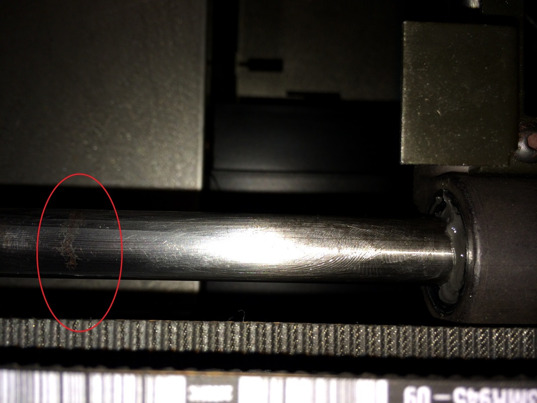
Looking closely at the guide rods, you could see evidence of surface corrosion. Wiping them down with WD-40 and a very mild Scotch-Brite pad took care of most of it in a flash.
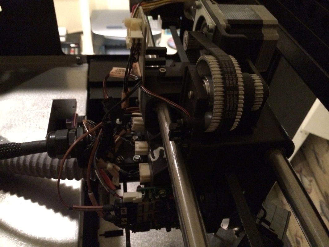
I loved digging into this! It was amazing to me how massive the head of this FDM machine was; it goes counter to many of today's consumer-grade printers that aim to keep the head as small and light as possible. I suppose anything is possible if you have motors beefy enough to push it around.
|
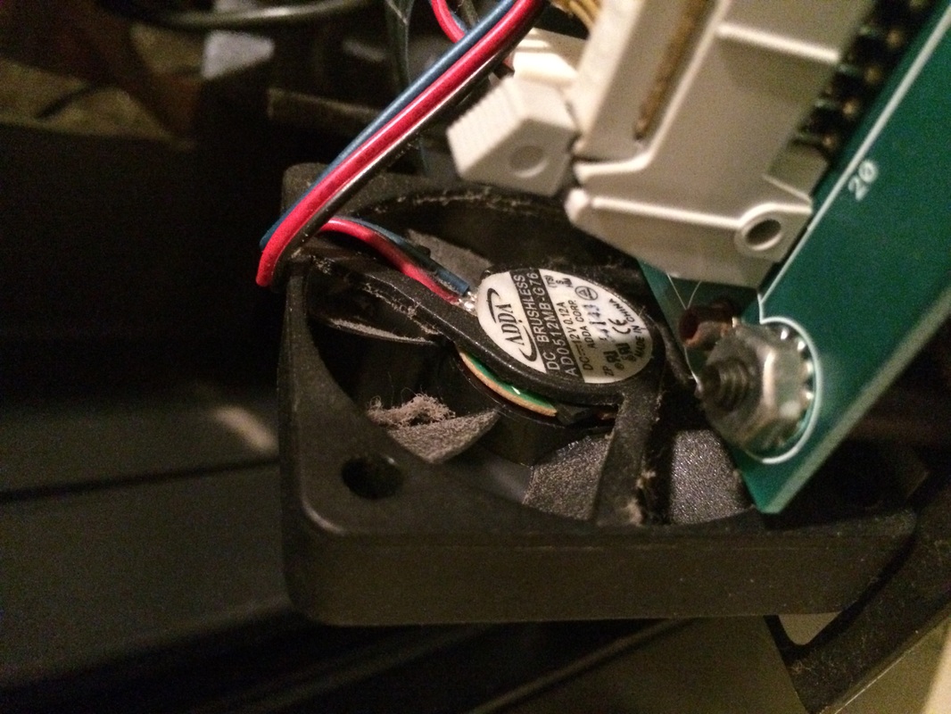
While the machine was open, I went ahead and replaced this small fan that was making a very annoying noise. Of course the fan was inconveniently buried deep with the front panel of the machine.
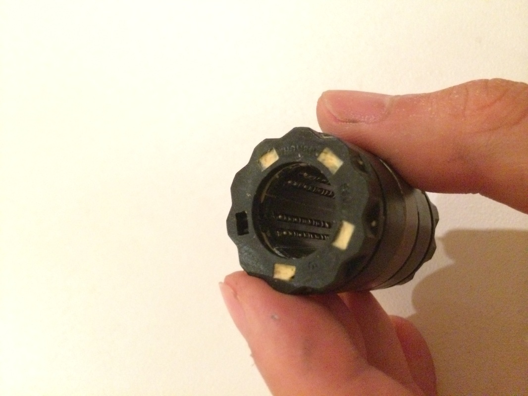
These linear bearings were the culprits. Once I had them out, I could clearly see that the balls no longer rolled, but instead slid against the shaft. No wonder that there was so much resistance, and why oiling the bejesus out of the printer helped for just a few moments!
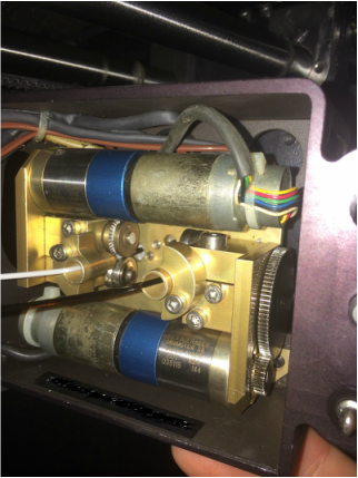
The inside of the head of the machine. These geared drive motors blew my mind.
|
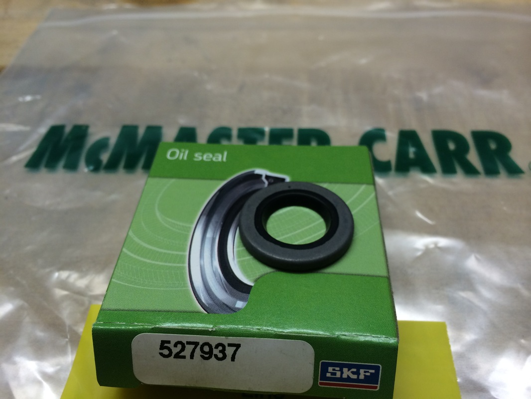
With the culprit bearings identified and removed, it was time to find replacements. The bearings matched up perfectly with a stock McMaster part. Instead of being secured with cir-clips, however, the bearings were held in place with the metal-rubber seals (oil seals) that also served to prevent bearing contamination. The parts that I had destroyed while removing the bearings... doh!
Finding replacement seals was not as easy as I had hoped. It turns out that the common seal thickness for 1.125" OD and 0.625" ID is 0.25" -- too thick for my application (the Stratasys seal was a mere 0.125" thick). After calling numerous local bearing and seal suppliers, and scouring the web for options, I was close to settling for the thicker seals, which I would partially press into place, leaving the rest hanging out of the carriage. Not ideal, for sure, but it would probably work. In a last ditch effort to find the correct part, I called McMaster and asked if they might be able to help me in sourcing the correct seal. Due to my affiliation through Vinnovation with super-customer Alex (of York Machine Works), McMaster was more than willing to help me out with the mission. Within 2 days the correct seals were shipped out, at only $5 a piece!
Finding replacement seals was not as easy as I had hoped. It turns out that the common seal thickness for 1.125" OD and 0.625" ID is 0.25" -- too thick for my application (the Stratasys seal was a mere 0.125" thick). After calling numerous local bearing and seal suppliers, and scouring the web for options, I was close to settling for the thicker seals, which I would partially press into place, leaving the rest hanging out of the carriage. Not ideal, for sure, but it would probably work. In a last ditch effort to find the correct part, I called McMaster and asked if they might be able to help me in sourcing the correct seal. Due to my affiliation through Vinnovation with super-customer Alex (of York Machine Works), McMaster was more than willing to help me out with the mission. Within 2 days the correct seals were shipped out, at only $5 a piece!
McMaster, I love you.
Finally it was time to rebuild the machine. Amazingly, I got almost everything done during one 7-hour marathon with a great (and patient) high school friend of mine. By the time he left around 2AM, the machine was put back together and building the first of many calibration parts that I would later use to tune the machine back to factory specs. Without question, the hardest part of the rebuild process was leveling the print head with respect to the print bed to within +/- 0.0015" over it's 8" square surface. For that task I had printed (on my 3D Touch) a simple tool to hold a dial indicator, which we used to measure the relative heights of the 4 corners of the build platform. Adjustments were made by turning cam-nuts that Stratasys had installed on 3 of the 4 corners connecting the XY table to the frame of the machine.
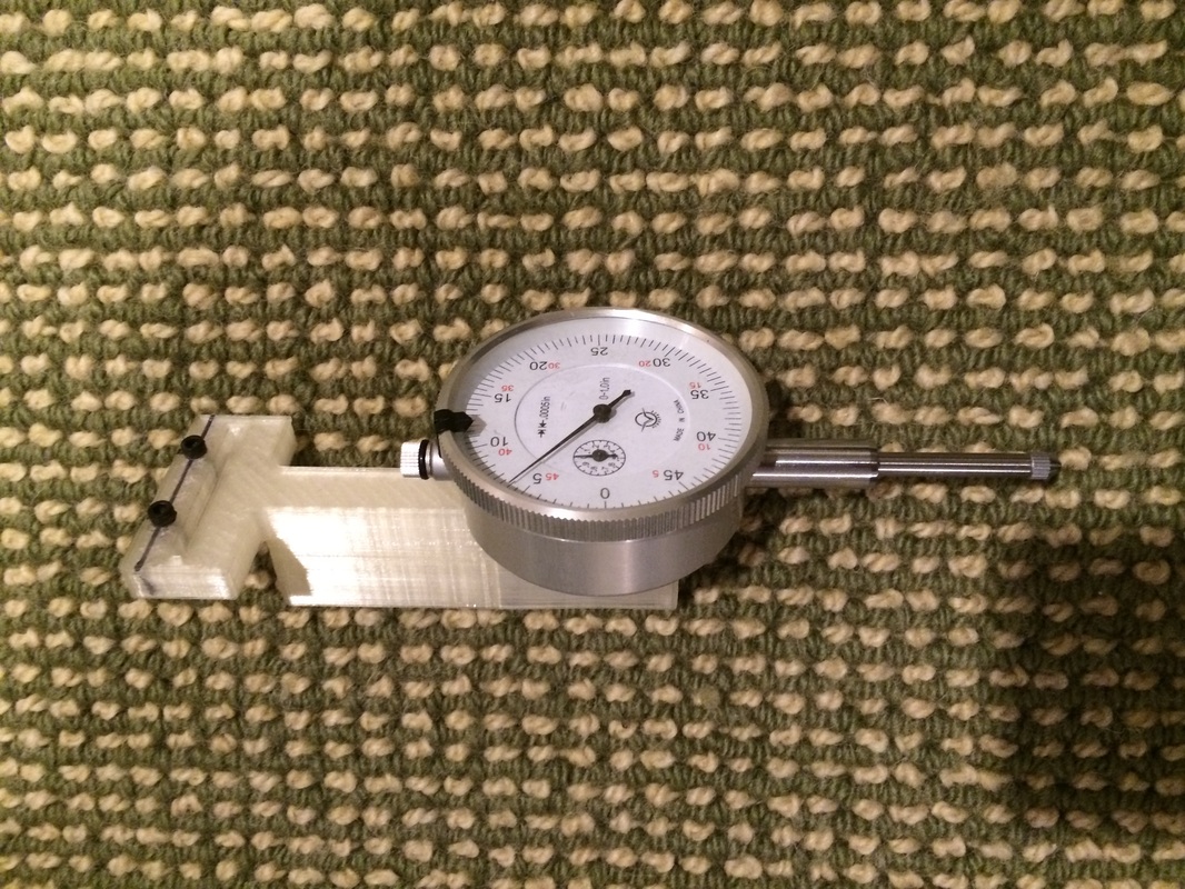
My home-brew dial indicator leveling tool.
|
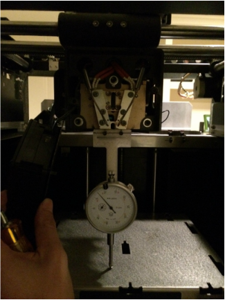
In action!
|
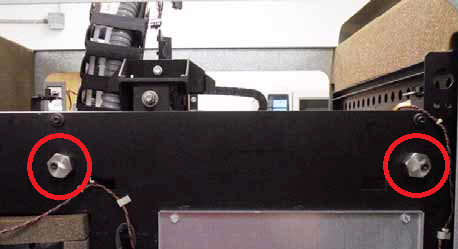
Adjusting these cam nuts allowed us to raise or lower a particular corner of the XY table relative to the frame (and print bed) of the machine.
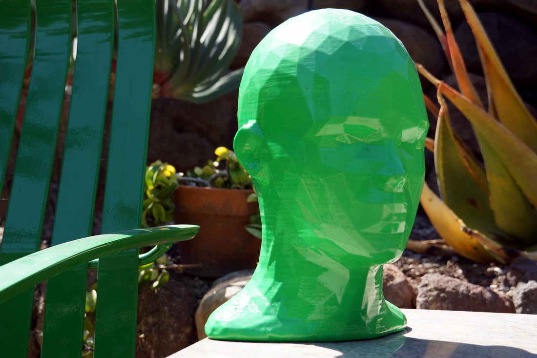
After all of the calibrations were done, the printer was working better than ever. The results speak for themselves!
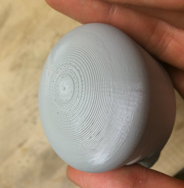
Gone are the days of funky top surfaces!
It's my hope that fixing up the Stratasys will only be the start of my exploring professional 3D printers. In addition to the mechanics of printing,
I'd also like to learn more about suitable FDM materials and how to use them properly. As discussed on the 3D Touch Modifications page, getting consumer-grade printers to behave reliably and print nicely -- especially with 2+ material builds, can be a real challenge. I've come to the conclusion that a big chunk of that problem can be solved with a deeper understanding of how the thermoplastics being extruded behave. My inspiration comes from the Stratasys machine: it uses a special ABS as well as soluble support material that stick to one another well, but not too well. Warping is minimized through the use of a heated build chamber, set to a temperature just below the glass transition temperature of either material. Wouldn't it be great to replicate the reliability and performance of those machines, ideally using materials like PLA that are inexpensive and versatile?
More updates to come soon!